Embedded Files
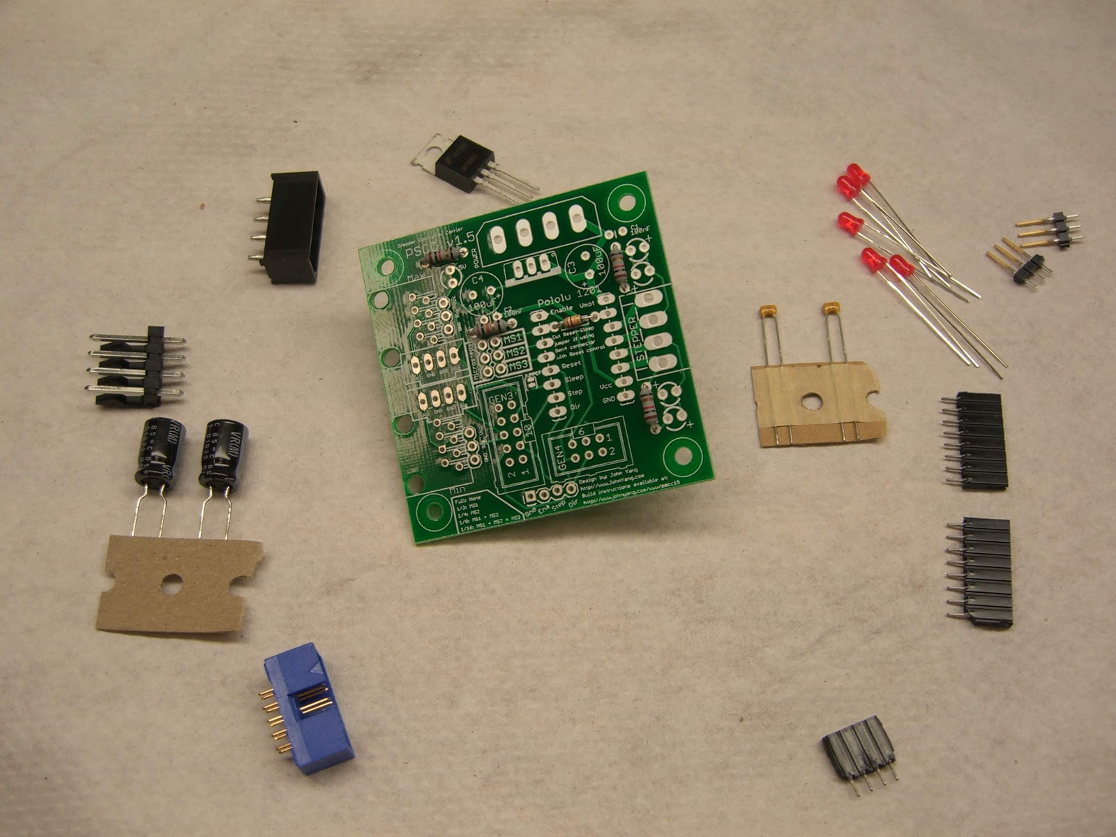
The pololu stepper controller carrier comes as a kit. Follow the directions below to put it together to be a drop in replacement for a makerbot/reprap stepper controller.
You can buy a Carrier Board kit from MakerGear here.
If you have questions, please email me at lj.johnyang*AT*gmail*DOT*com

Bill of Materials (BOM)
To assemble this kit, you will need some tools. You will need a soldering iron, solder, cutters, and a pcb holder or other means of holding the board as you solder. The instructions below assume you have basic soldering experience. If you do not, please review this tutorial first to get acquainted with soldering basics and safety.
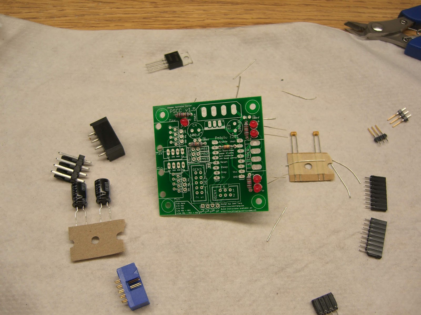
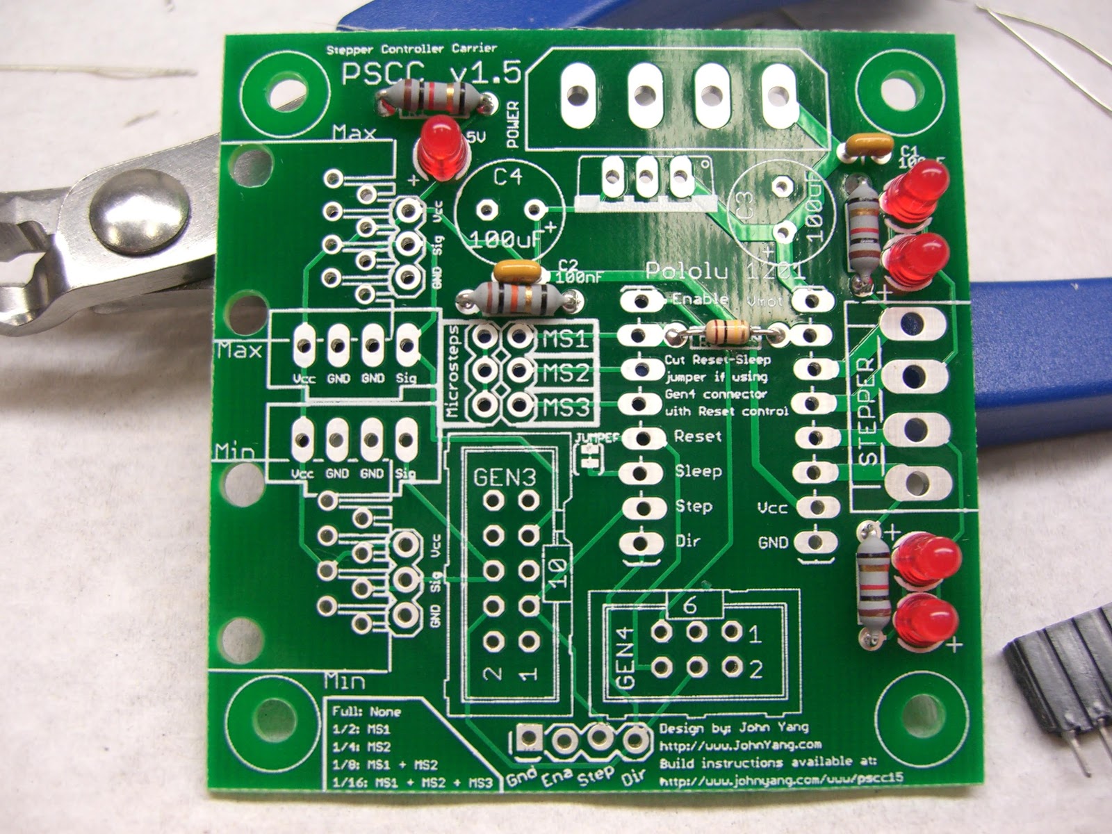
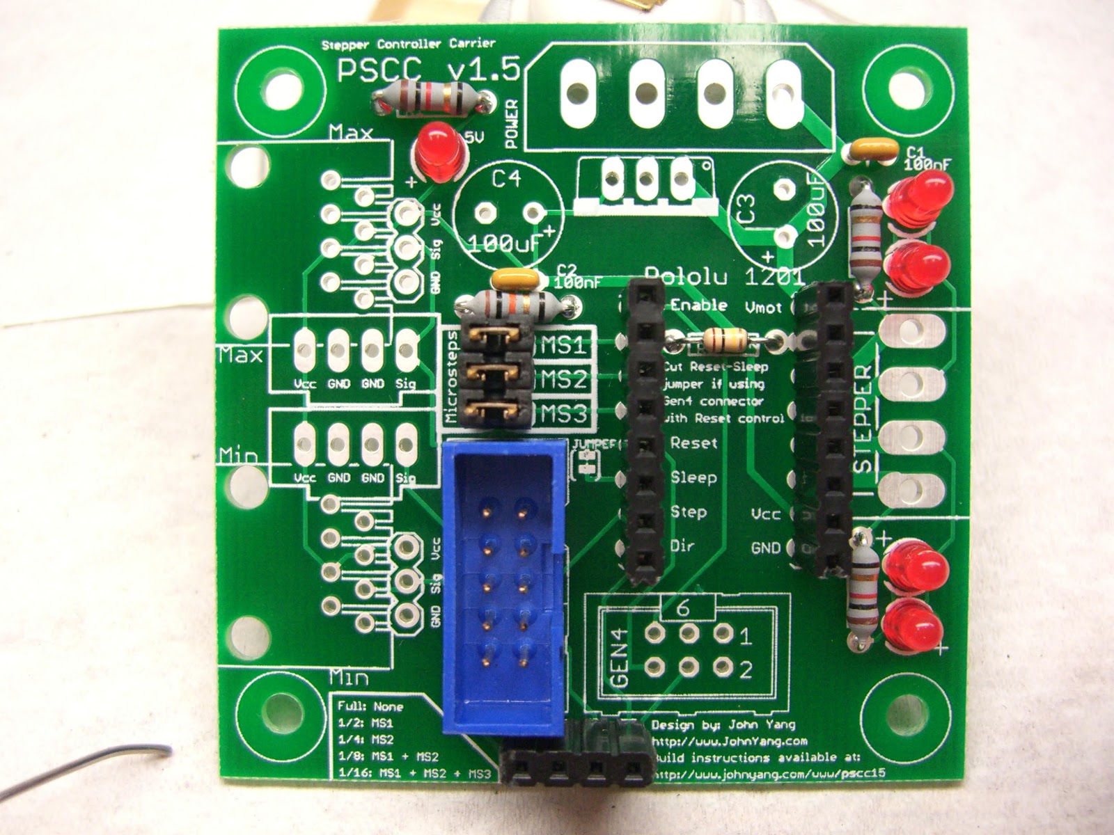
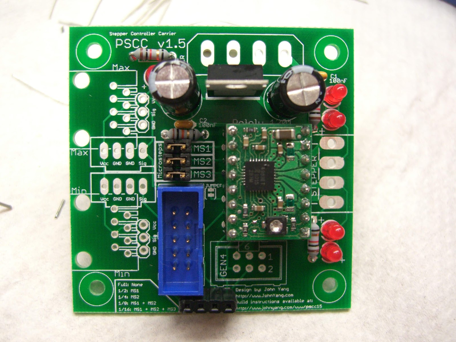
Resistors go in first. R1,R4,R5 get 1k Ohm (brown-black-red-gold) resistors. R2 gets the 10k Ohm (brown-black-orange-gold) resistor. R3 gets the 100k Ohm (brown-black-yellow-gold) resistor.
LEDs go in next. Ensure the polarity is correct for each LED. Each location has a small + on the silkscreen next to the hole that should receive the positive leg. The positive leg is the longer one on an LED. If you have 3 red and 2 green LEDs, insert the green led in the top most location and the bottom most location on the right hand side of the board. The four LEDs by the stepper connector indicate which direction the coils are energized, and the different colors help identify this.
Ceramic capacitors go in next, these are not polarized. These go in the C1 and C2 locations.
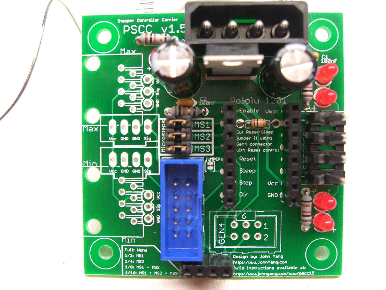
Gen3 connector goes in next. Make sure to match up the key in the silkscreen with the notch in the part. If you are using the Gen4 connector, you can install that at this time too. If you want discrete access to the enable, step and direction pins, solder in a 4-pin header below the Gen3 and Gen4 header locations on the bottom of the board.
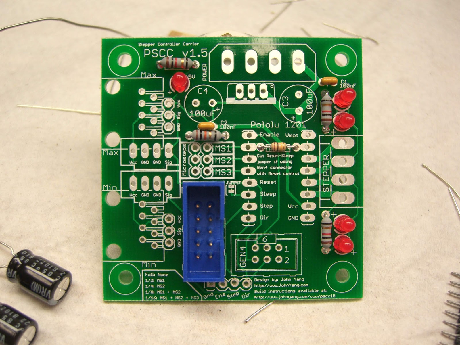
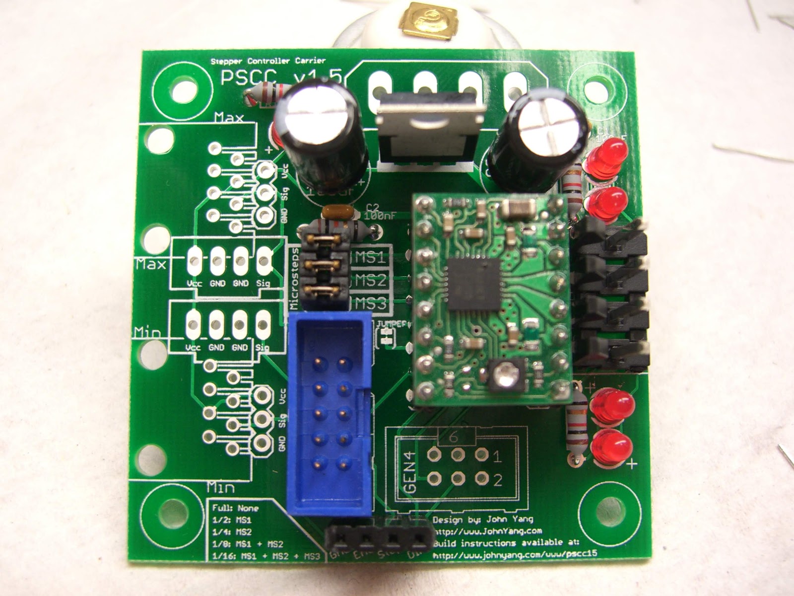
Jumper block and pin headers go in next. If you have a 2x3 jumper block, you're set, but if you have two 1x3 strips for the jumpers, you'll want to connect the two 1x3 strips together with the jumpers/shunts so that they are aligned while you solder them. This will ensure that the jumper/shunt will fit when the two 1x3 strips are in place.
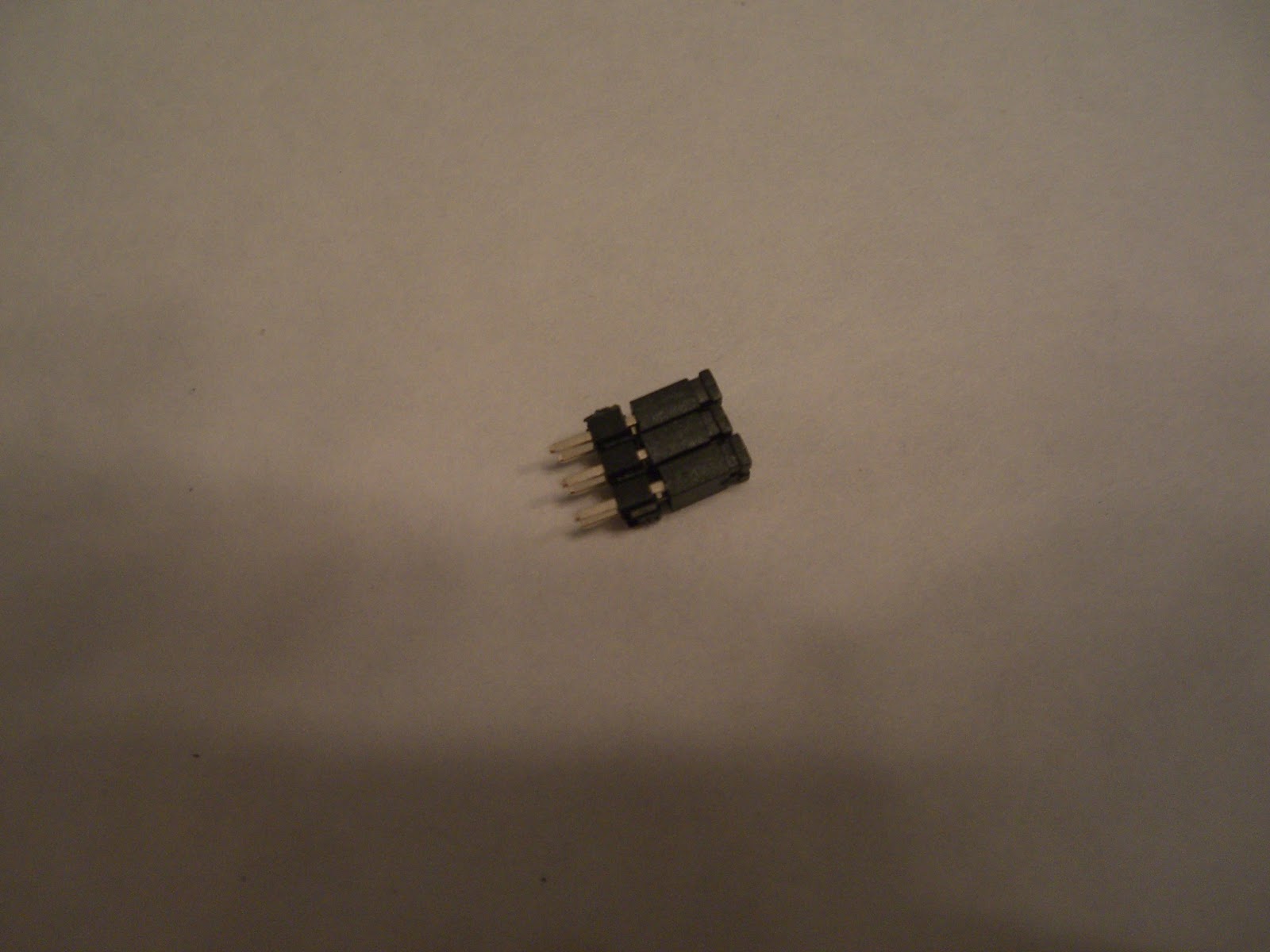
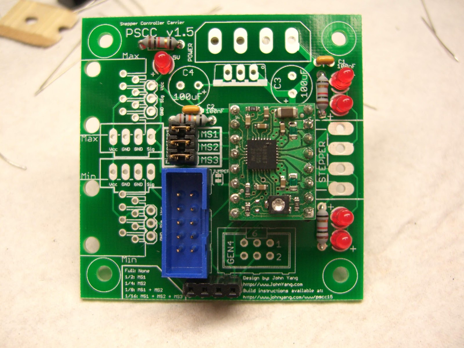
When soldering in the two 8-pin headers, insert in the pololu module while you solder so you are sure the headers are aligned, this will ensure that the headers are straight and that the module will fit.
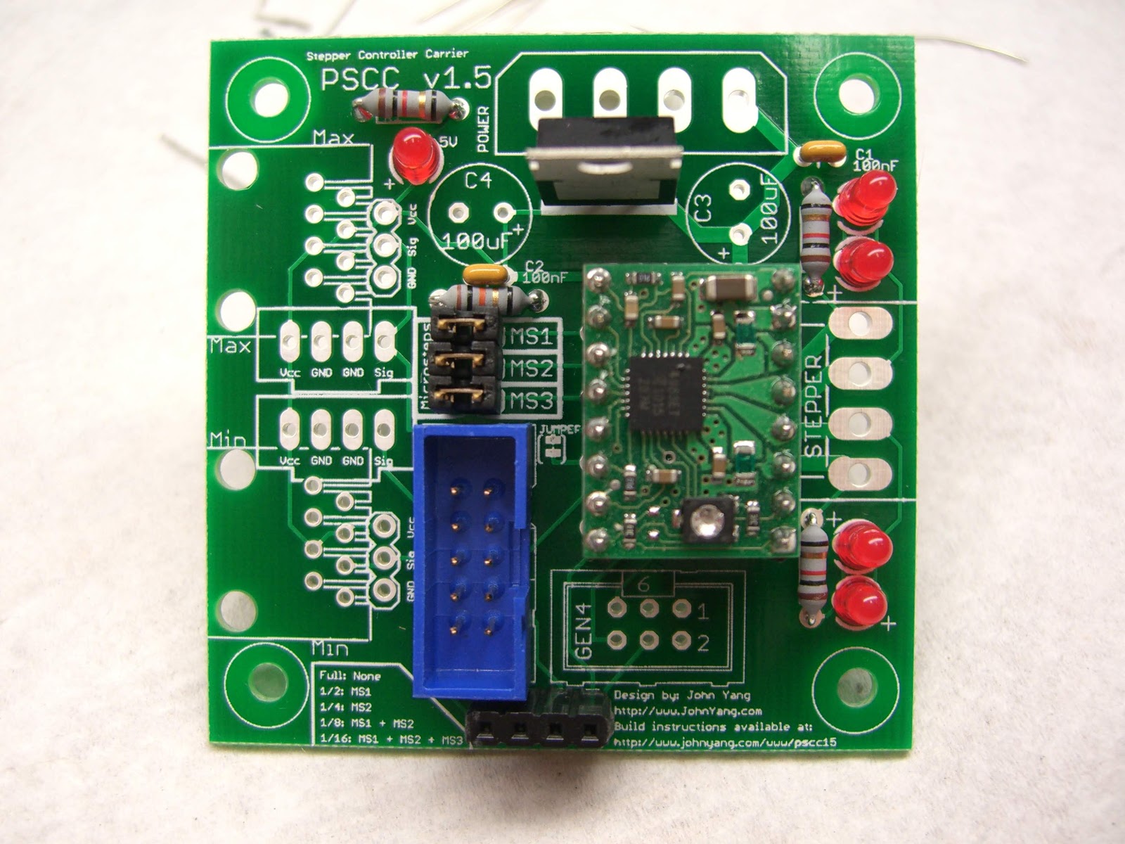
7805 voltage regulator goes in next. Make sure he metal tab matches the bar on the silkscreen. It should point away from the 4-pin power connector.
Aluminum electrolytic capacitors go in next in locations C3 and C4. Pay close attention to the polarity as you insert them. The silkscreen has a plus sign (+) next to the positive side. The positive leg is longer on the part. The electrolytic capacitors also have a marking on the case for the negative side as well.
The stepper connector goes in next, make sure the key portion of the connector matches the silkscreen, it should be next to the 8 pin header for the Pololu module.
The power connector goes in next, match up the silkscreen with the keying on the connector. The angled corners of the connector should match the angled lines on the silkscreen.
Reinsert the pololu module and you are done.
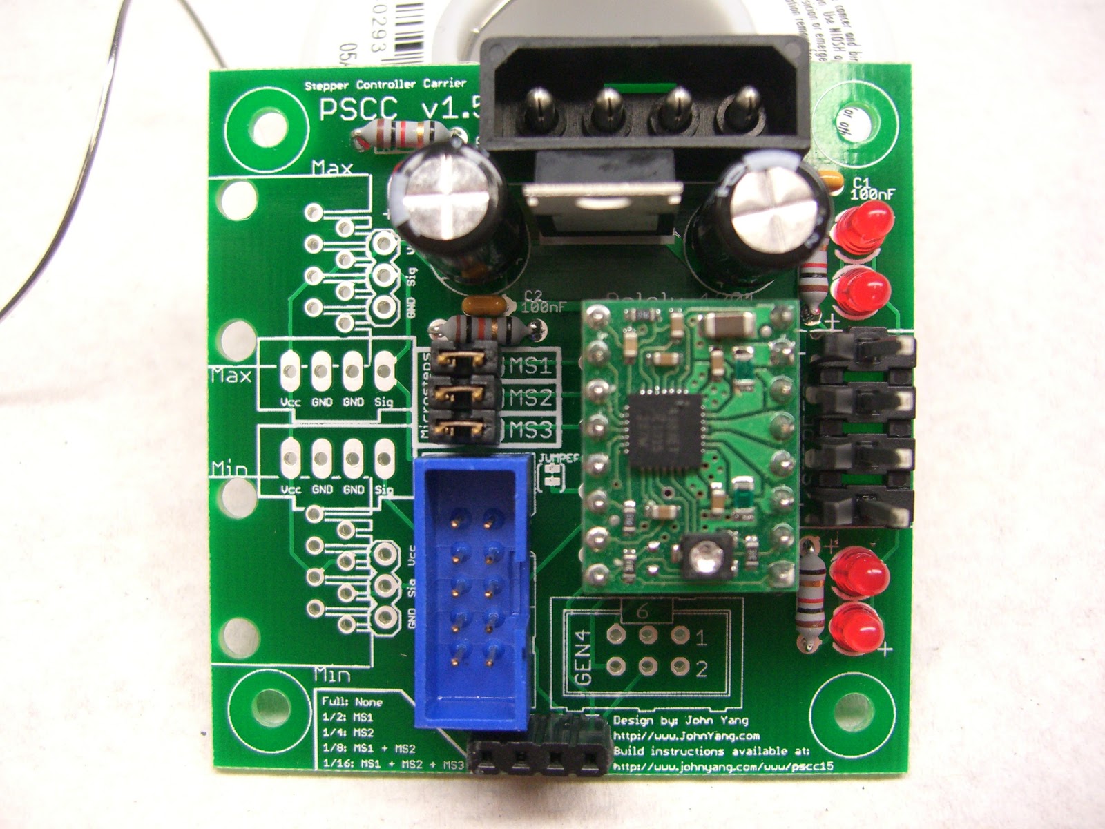
Apply a heatsink to the chip on the Pololu module to help with heat.
If you want to use the board with Gen4 electronics, you will want to populate the Gen4 location on the board with a shrouded 2x3 6-pin connector.
If you want to use endstops with the stepper driver, you can connect RJ45 jacks to the Min and Max locations for use with gen3 style opto-endstops, or cdrom connectors for gen4 style mechanical endstops or 3-pin headers for custom connections to your endstops.
To change the repplicatorg to use 1/8 or 1/16 step, you have to modify your machines.xml file. Change the line for your machine definition that look like the following:
<axis id="x" length="300" maxfeedrate="5000" scale="11.4485"/>
<axis id="y" length="300" maxfeedrate="5000" scale="11.4485"/>
<axis id="z" length="300" maxfeedrate="300" scale="320"/>
to reflect the new scale you have. The scale value above assumes the MBI stepper controller 1/2 stepping configuration.
To go to 1/4, change to
<axis id="x" length="300" maxfeedrate="5000" scale="23.534926"/>
<axis id="y" length="300" maxfeedrate="5000" scale="23.534926"/>
<axis id="z" length="300" maxfeedrate="300" scale="640"/>
To go to 1/8, change to
<axis id="x" length="300" maxfeedrate="5000" scale="47.069852"/>
<axis id="y" length="300" maxfeedrate="5000" scale="47.069852"/>
<axis id="z" length="300" maxfeedrate="300" scale="1280"/>
To go to 1/16, change to
<axis id="x" length="300" maxfeedrate="5000" scale="94.139704"/>
<axis id="y" length="300" maxfeedrate="5000" scale="94.139704"/>
<axis id="z" length="300" maxfeedrate="300" scale="2560"/>
and if you want to run the Z at a different microstepping rate, just set the jumpers and choose the right setting for the Z scale value. For full step in the Z axis, set scale=160 for the Z line.
For stepper extruder connections on a makerbot, you will have to use jumpers to the ground, enable, step and direction pins. These four pins are broken out underneath the Gen3/Gen4 shrouded connectors. Use a Male or Female 4 pin header and connect your jumper wire from the Extruder Controller pins to the appropriate pin on the stepper controller.
There is a truth table in the lower left corner of the board with the jumper settings for the different microstepping options.
If you have questions, please email me at lj.johnyang*AT*gmail*DOT*com
Report abuse