Embedded Files
The pololu stepper controller carrier comes as a kit. Follow the directions below to put it together to be a drop in replacement for a makerbot stepper controller. If you have a mendel or custom connectors for your electronics, you can add in 0.1" headers or terminal blocks to the endstop/control/stepper connections instead of (or in addition to) the supplied connectors. The instructions below assume some prior soldering experience. If you have not soldered anything before, please read this tutorial and acquaint yourself with proper soldering techniques and safety precautions.
I have a few of these kits still available if you're interested. Contact me at the address below for details.
If you have questions, please email me at lj.johnyang*AT*gmail*DOT*com
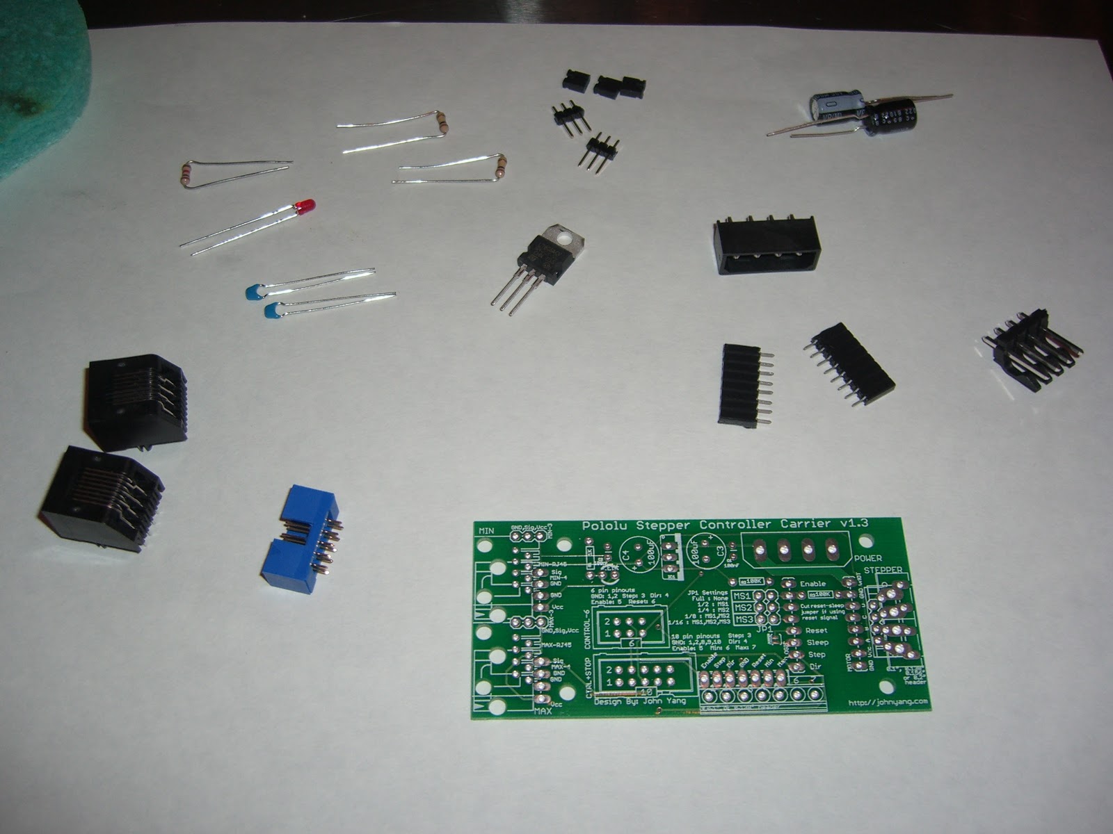
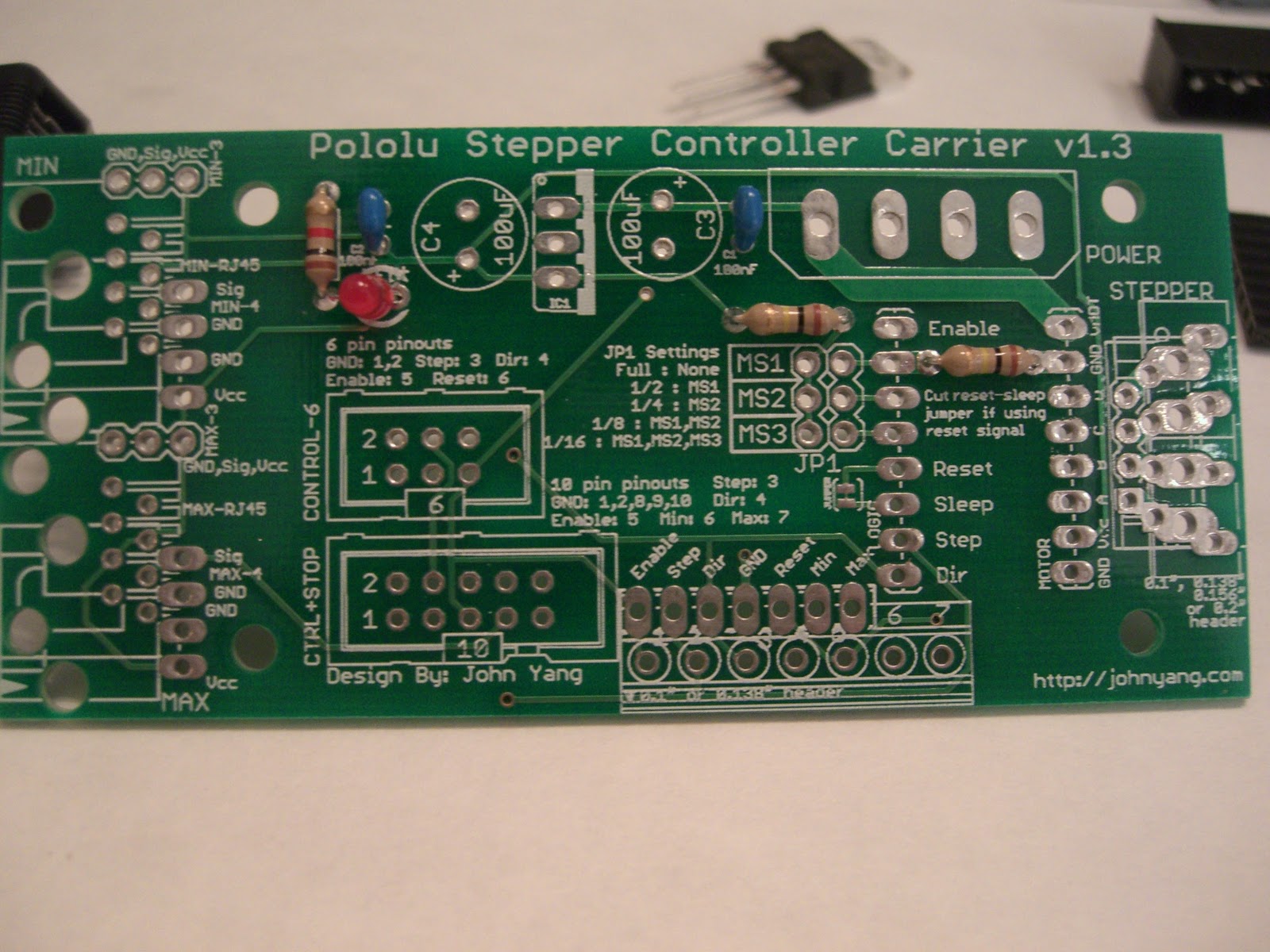
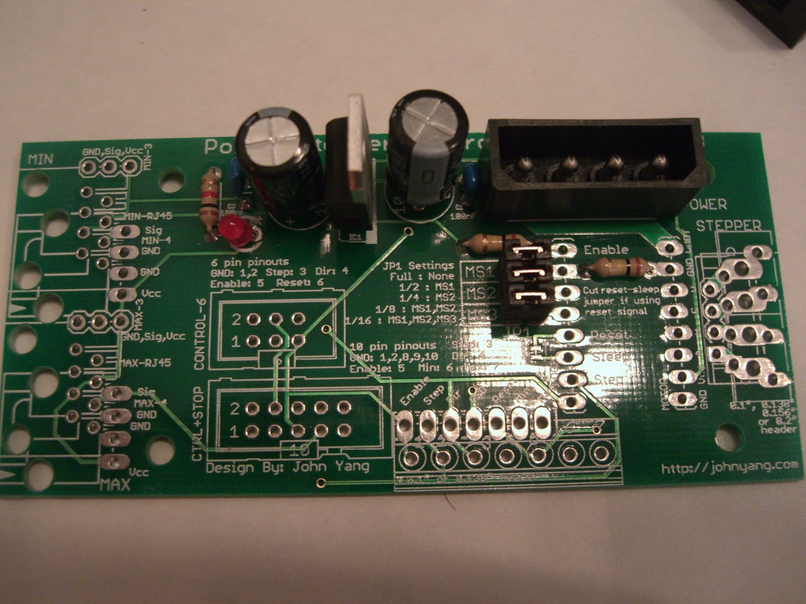
Resistors, led and ceramic capacitors go in first. The 1k ohm resistor (brown-black-red-gold) goes in R1, 10k ohm (brown-black-orange-gold) goes in R2 and 100k ohm (brown-black-yellow-gold) goes in R3. The silkscreen has the wrong value for R2 printed on the board. R2 should be the 10k ohm resistor. The LED is polarized, the long leg (positive) goes to the right side of the board. The ceramic capacitors go in C1 and C2. Bend the leads and solder everything to the board and trim the excess leads. There was a mistake in the silkscreen, R2 should be a 10k ohm resistor, not the 100k that is marked on the board.
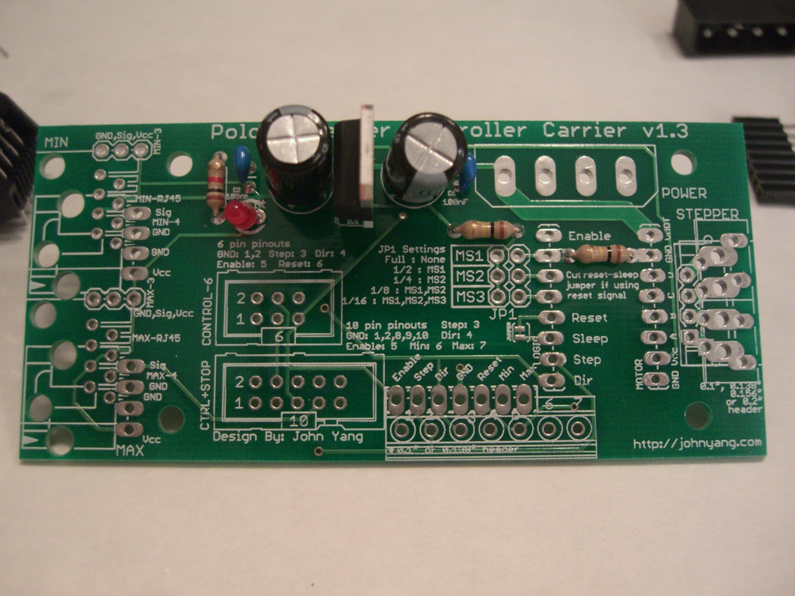
The electrolytic capacitors and the power regulator go in next. The electrolytic capacitors are polarized and need to be put in the correct way. C3 has the positive side (long leg) towards the top of the board. C4 has the positive side (long leg) towards the bottom of the board. The 7805 regulator goes in the board with the metal tab on the right hand side.
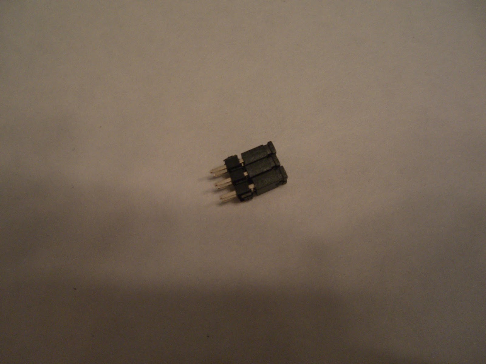
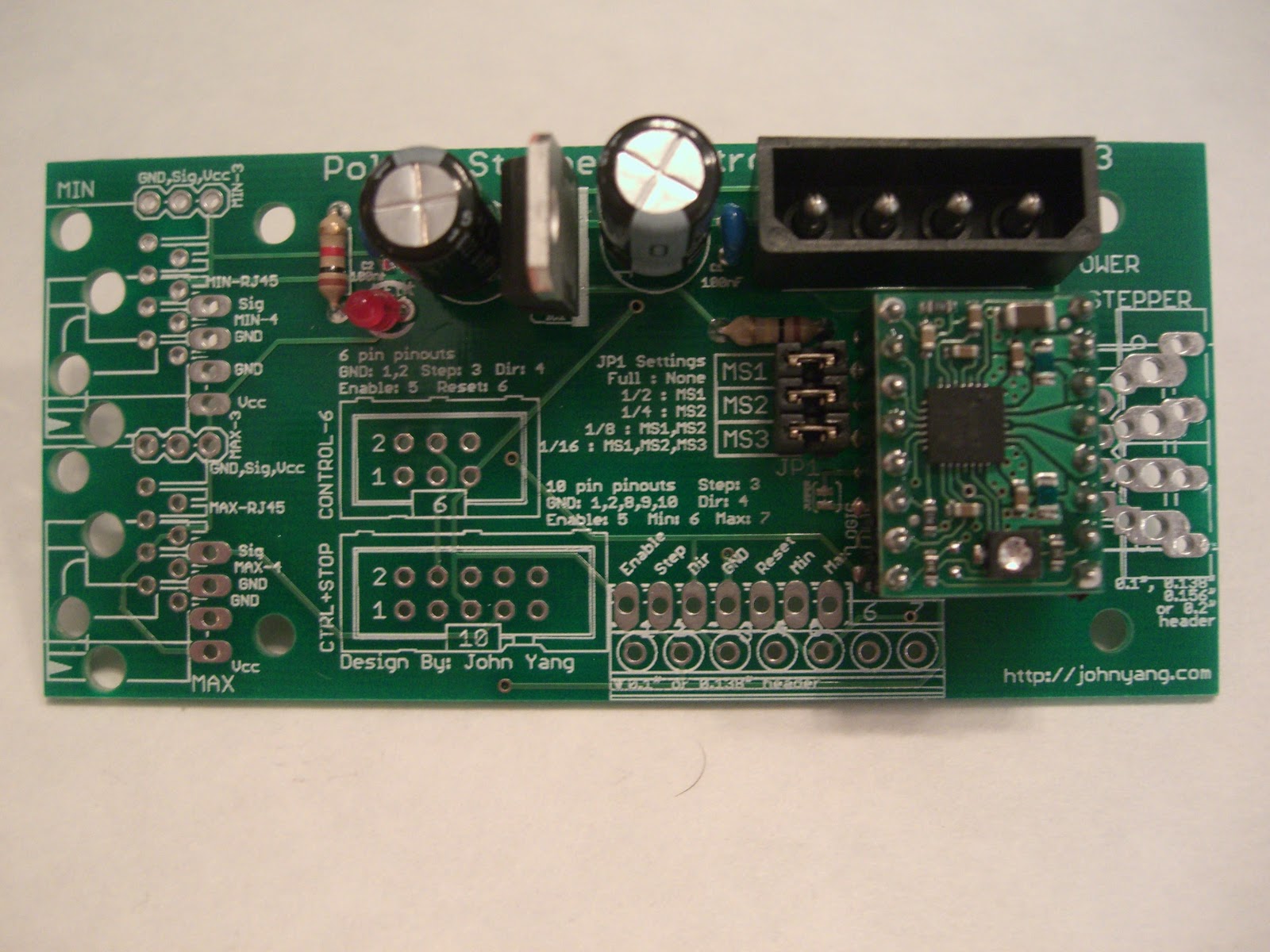
Jumpers go in next. You'll want to put together the two 3 pin headers with the 3 jumpers so that they are one unit or use a 2x3 6-pin header. Then place the whole unit in the 6 pin holes for JP1. Use some tape to hold them flat to the board while you turn the board over to solder it in. Also solder in the power connector. Match up the silkscreen with the keying on the connector to make sure it is put in the correct way.
solder the 8-pin headers to the pololu controller. (no picture) Make sure the pins are parallel, use a breadboard to hold the two pin strip headers while you solder the pololu to them. This will make sure they are vertical and will fit.
The two 8-pin socket headers are next. To make sure the pololu will fit, place the sockets on the pins of the pololu, then place the whole unit into the controller and solder. This will ensure that the pololu will fit the female sockets. Make sure the pinouts on the pololu driver match the pinouts on the controller board silkscreen, make sure you don't put it in the wrong way.
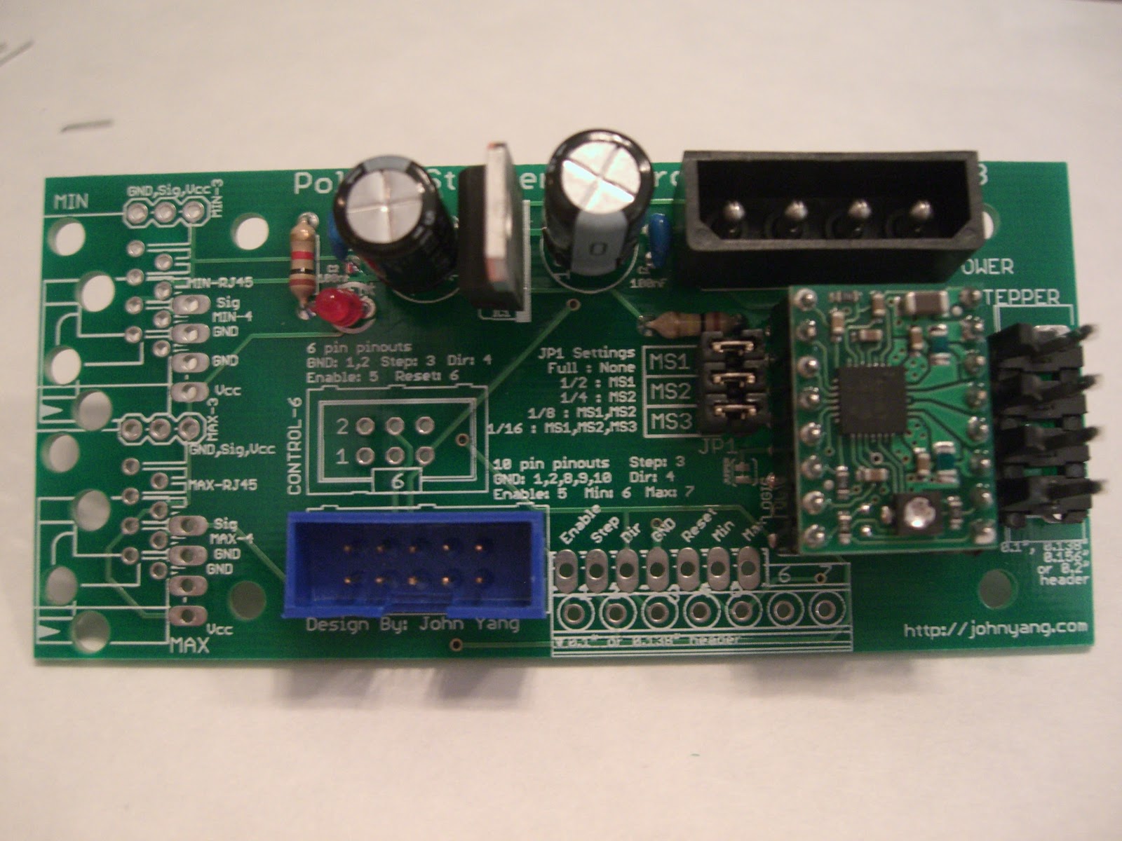
The 10 pin shrouded header and the 4 pin molex header are next. The hole in the 10 pin header shroud goes toward the bottom of the controller, following the silkscreen image. The friction holders of the 4 pin stepper connector go towards the left near the pololu.
The rj45 connectors are the final connections. The two rj45 jacks snap into the board, and are soldered in place.
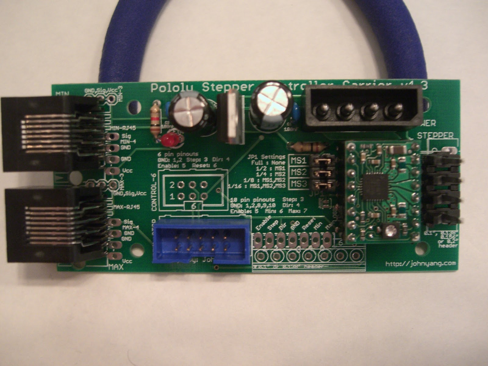
Apply the adhesive to the heatsink and stick it to the chip on the pololu being careful not to touch/short any pins or components. If you are worried, you can wrap the edges of the heatsink with tape to insulate it from any electrical connections it may make if you are not careful.
(Picture coming soon)
To change the repplicatorg to use 1/8 or 1/16 step, you have to modify your machines.xml file. Change the line for your machine definition that look like the following:
<axis id="x" length="300" maxfeedrate="5000" scale="11.4485"/>
<axis id="y" length="300" maxfeedrate="5000" scale="11.4485"/>
<axis id="z" length="300" maxfeedrate="300" scale="320"/>
to reflect the new scale you have. The scale value above assumes the MBI stepper controller 1/2 stepping configuration.
To go to 1/4, change to
<axis id="x" length="300" maxfeedrate="5000" scale="23.534926"/>
<axis id="y" length="300" maxfeedrate="5000" scale="23.534926"/>
<axis id="z" length="300" maxfeedrate="300" scale="640"/>
To go to 1/8, change to
<axis id="x" length="300" maxfeedrate="5000" scale="47.069852"/>
<axis id="y" length="300" maxfeedrate="5000" scale="47.069852"/>
<axis id="z" length="300" maxfeedrate="300" scale="1280"/>
To go to 1/16, change to
<axis id="x" length="300" maxfeedrate="5000" scale="94.139704"/>
<axis id="y" length="300" maxfeedrate="5000" scale="94.139704"/>
<axis id="z" length="300" maxfeedrate="300" scale="2560"/>
and if you want to run the Z at a different microstepping rate, just set the jumpers and choose the right setting for the Z scale value. For full step in the Z axis, set scale=160 for the Z line.
If you have questions, please email me at lj.johnyang*AT*gmail*DOT*com
Report abuse